
Seven segment displays are used to indicate numerical information. Seven segments display can display digits from 0 to 9 and even we can display few characters like A, b, C, H, E, e, F, etc. These are very popular and have many more applications. Before going to start this concept, get an idea about how to interface LEDs with 8051 Microcontroller.
This article describes you how to interface seven segments to AT89C51 microcontroller. This system displays the digits from 0 to 9 continuously with a predefined delay.
Interfacing 7 Segment Display to 8051 Circuit Principle:
Seven segment displays internally consist of 8 LEDs. In these LEDs, 7 LEDs are used to indicate the digits 0 to 9 and single LED is used for indicating decimal point. Generally seven segments are two types, one is common cathode and the other is common anode.
Important Related Post – Water Level Indicator Project Complete Documentation
Important Related Post – Water Level Indicator Project Complete Documentation
In common cathode, all the cathodes of LEDs are tied together and labeled as com. and the anode are left alone. In common anode, seven segment display all the anodes are tied together and cathodes are left freely. Below figure shows the internal connections of seven segment Display.
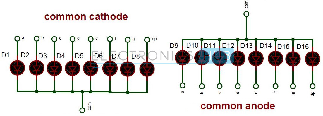
Internal Connections of Seven Segment
Interfacing 7 Segment Display to 8051 Circuit Diagram:
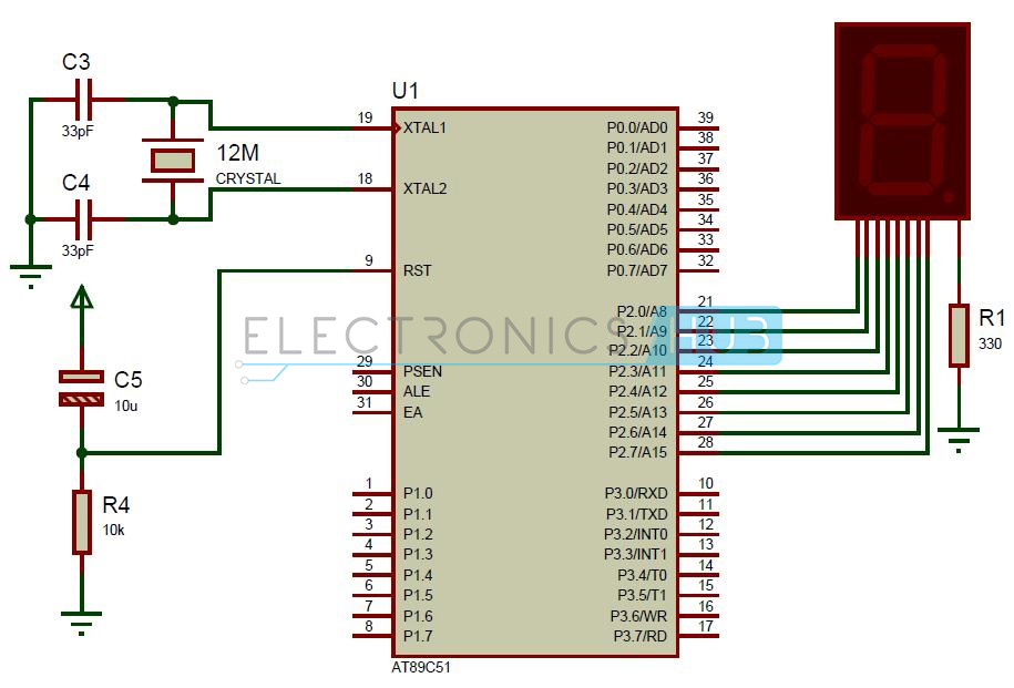
Circuit Diagram of Interfacing 7 Segment Display to 8051 Microcontroller
Circuit Components:
- AT89C51 microcontroller
- AT89C51 programming board
- programming cable
- 12V DC battery or adaptor
- Common cathode 7 segment Display
- Resistors – 10k, 330 ohm
- 2 Ceramic capacitors – 33pF
- 12 MHz crystal
- Electrolytic capacitor – 10uF
- Connecting wires.
Interfacing 7 Segment Display to 8051 Circuit Design:
Here, common cathode seven segment is used to display the digits. In this circuit, pins a to h of the 7 segment are connected to the PORT 2 of the microcontroller and com pin is connected to the ground through the 330 ohm resistor. This resistor is used to drop the voltage. Since we are using common cathode seven segment we need to send LOGIC 1 to the segments to glow.
Figure shows structure of common cathode seven segments. Here dot is used for indicating the decimal point. Here all the cathodes of LED’s are connected to the Gnd pin. The operating voltage of this LED’s is 2 to 3V but from controller we will get 5V so to drop the remaining voltage we have to connect a to g pins to the controller through the resistor.
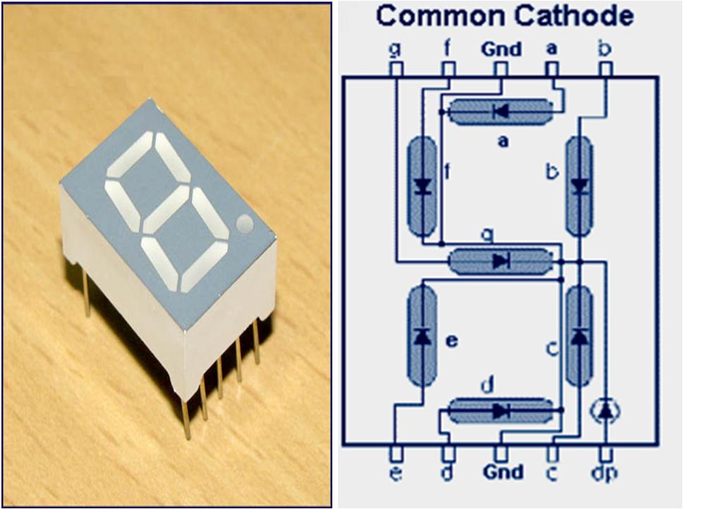
Common cathode 7 segment Display
Digit Drive Pattern:
To display the digits on 7 segment, we need to glow different logic combinations of segments. For example if you want to display the digit 3 on seven segment then you need to glow the segments a, b, c, d and g. The below table show you the Hex decimal values what we need to send from PORT2 to Display the digits from 0 to 9.
Algorithm:
- First initialize all the segment hex values of the digits in an array.
unsigned char arr[10]={0x3f,0x06,0x5b,0x4f,0x66,0x6d,0x7d,0x07,0x7f,0x67};
- Now take for loop and assign array values to the PORT2 with some time delay.
for (i=0;i<10;i++)
{
P2=arr[i];
delay_ms(500);
}
How to Operate Interfacing 7 Segment Display to 8051 Circuit?
- Initially burn the program to the microcontroller
- Give the connections as per the circuit diagram
- Make sure that a to g pins of 7 segment are connected to the P2.0 to P2.6 respectively.
- Switch on the supply, you can observe that digits 0 to 9 will display continuously with some delay.
- Switch of the supply.
Interfacing 7 Segment Display to 8051 Circuit Applications:
- Seven segments are widely used in digital clocks to display the time.
- These are used in electronic meters for displaying the numerical information.
- Used in Instrument panels
- Used in digital readout displays.
Limitations of the Circuit:
- The complexity is increased to display large information.
- It is not possible to display the symbols on seven segment.
0 comments:
Post a Comment