
Light Emitting Diodes are the mostly commonly used components in many applications. They are made of semiconducting material. This article describes about basic interfacing of LEDs to the 8051 family microcontrollers.

Image – ElectronicsHub.org
LED Interfacing with 8051 Circuit Principle:
The main principle of this circuit is to interface LEDs to the 8051 family micro controller. Commonly, used LEDs will have voltage drop of 1.7v and current of 10mA to glow at full intensity. This is applied through the output pin of the micro controller.
LED Interfacing of 8051 Microcontroller Circuit Diagram:
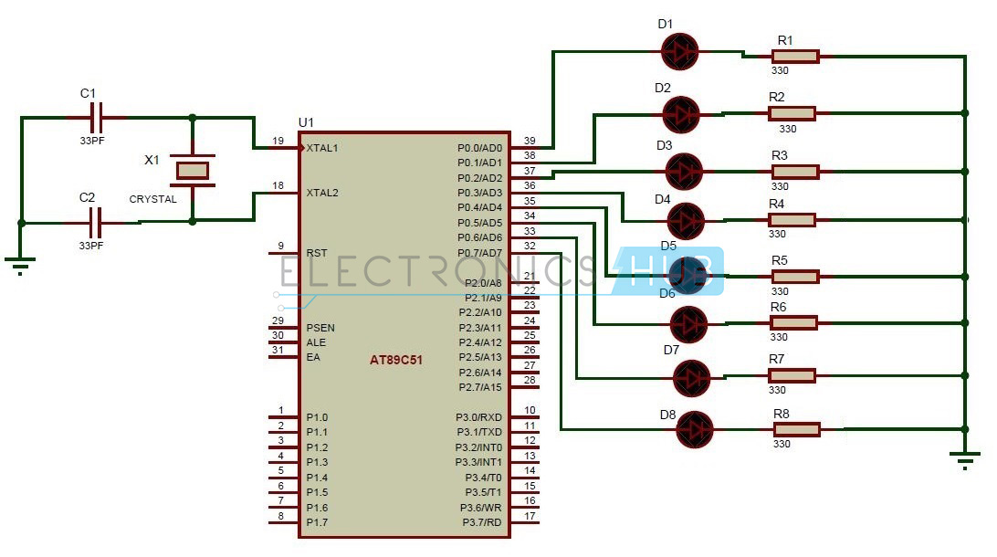
Circuit Diagram of Interfacing LEDs to 8051 Microcontroller
Circuit Components:
- AT89C51 microcontroller.
- 8 LEDs – D1 to D8.
- 8 Resistors – R1 to R8.
- Crystal oscillator.
- 2 Capacitors – C1 and C2.
LED Interfacing with 8051 Microcontroller Circuit Design:
The circuit mainly consists of AT89C51 microcontroller. AT89C51 belongs to the family of 8051 microcontroller. It is an 8-bit microcontroller. This microcontroller has 4KB of Flash Programmable and Erasable Read Only Memory and 128 bytes of RAM. This can be programmed and erased maximum 1000times. It has two 16 bit timers/counters. It supports USART communication protocol. It has 40 pins. There are four ports are designated as P0, P1, P2, P3, P4. In this circuit, LEDs are connected to the port P0. Port P0 will not have internal pull- ups, while the other ports have internal pull-ups. The controller is connected with external crystal oscillator to pin 18 and 19 pins. Crystal pins are connected to the ground through capacitors of 33pf.
Related Post – Interfacing 7 Segment Display to 8051 Microcontroller
Related Post – Interfacing 7 Segment Display to 8051 Microcontroller
Light Emitting Diodes are the semi conductor light sources. Commonly used LEDs will have a cut-off voltage of 1.7V and current of 10mA. When an LED is applied with its required voltage and current it glows with full intensity. The Light Emitting Diode is similar to the normal PN diode but it emits energy in the form of light. The colour of light depends on the band gap of the semiconductor. The following figure shows “how an LED glows?”
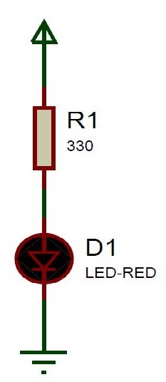
Thus, LED is directly connected to the AT89C51 microcontroller. The negative terminal of the LED is connected to the ground through a resistor. Value of this resistor is calculated using the following formula.
R= (V-1.7)/10mA, where V is the input voltage.
Generally, microcontrollers output a maximum voltage of 5V. Thus the value of resistor calculated for this is 330 Ohms. Thus this can be connected either to the cathode or anode of the LED.
How to Operate LED Interfacing with 8051 Microcontroller Circuit?
- Initially, burn the code into the microcontroller.
- Now, connect the LEDs to the port0 of the microcontroller.
- Switch on the circuit.
- Thus one can observe LEDs glowing.
- Now, switch off the circuit.
Algorithm for Interfacing LEDs to 8051 microcontroller:
- Initially, include the “reg51.h” header file in your code.
- Now write a function for producing delay using for loop.
- Start the main function.
- Inside the while loop write the condition to port pin for making it logic high or low.
- Initially, make it high for some delay of 500 seconds.
- Now make the port pin low.
- Again give some delay of 500 seconds.
- Thus LED starts glowing with a delay of 500 seconds.
- Now close the while loop and also main.
LED Interfacing with 8051 Circuit Applications:
- LEDs are widely used in many applications like in seven segments.
- They are used in dot matrix displays.
- They can be used for street lights.
- They are used as indicators.
- They can be used in traffic lights.
- They are used in emergency lights
- They can used to make electronic designs.
0 comments:
Post a Comment