
A regulated power supply is very much essential for several electronic devices due to the semiconductor material employed in them have a fixed rate of current as well as voltage. The device may get damaged if there is any deviation from the fixed rate. The AC power supply gets converted into constant DC by this circuit. By the help of a voltage regulator DC, unregulated output will be fixed to a constant voltage. The circuit is made up of linear voltage regulator 7805 along with capacitors and resistors with bridge rectifier made up from diodes. From giving an unchanging voltage supply to building confident that output reaches uninterrupted to the appliance, the diodes along with capacitors handle elevated efficient signal conveyal.
Description:
As we have previously talked about that regulated power supply is a device that mechanized on DC voltages and also it can uphold its output accurately at a fixed voltage all the time although if there is a significant alteration in the DC input voltage.
ICs regulator is mainly used in the circuit to maintain the exact voltage which is followed by the power supply. A regulator is mainly employed with the capacitor connected in parallel to the input terminal and the output terminal of the IC regulator. For the checking of gigantic alterations in the input as well as in the output filter, capacitors are used. While the bypass capacitors are used to check the small period spikes on the input and output level. Bypass capacitors are mainly of small values that are used to bypass the small period pulses straightly into the Earth.
A circuit diagram having regulator IC and all the above discussed components arrangement revealed in the figure below.
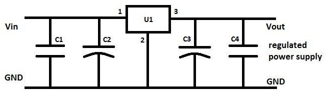
Regulated Power Supply Circuit
The working of the components coupled in the circuit above is revealed in the following table:
| This capacitor is known as bypass capacitor and is employed to bypass extremely tiny duration spikes to the ground with no distress the other components. | |
| C2 is the filter capacitor employed to steady the slow changes in the voltage applied at the input of the circuit. Escalating the value of the capacitor amplify the stabilization as well as the declining value of the capacitor reduces the stabilization. Moreover this capacitor is not alone capable to ensure very constricted period spikes emerge at the input. | |
| C3 is known as a filter capacitor employed in the circuit to steady the slow alterations in the output voltage. Raising the value of the capacitor enlarges the stabilization furthermore declining the value of the capacitor declined the stabilization. Moreover this capacitor is not alone capable to ensure very fine duration spikes happen at the output. | |
| C4 is known as bypass capacitor and worked to bypass very small period spikes to the earth with no influence the other components. | |
| U1 is the IC with positive DC and it upholds the output voltage steady exactly at a constant value even although there are major deviation in the input voltage. |
As we have made the whole circuit till now to be operated on the 5V DC supply, so we have to use an IC regulator for 5V DC. And the most generally used IC regulators get into the market for 5V DC regulation use is 7805. So we are connecting the similar IC in the circuit as U1.
IC 7805 is a DC regulated IC of 5V. This IC is very flexible and is widely employed in all types of circuit like a voltage regulator. It is a three terminal device and mainly called input , output and ground. Pin diagram of the IC 7805 is shown in the diagram below.
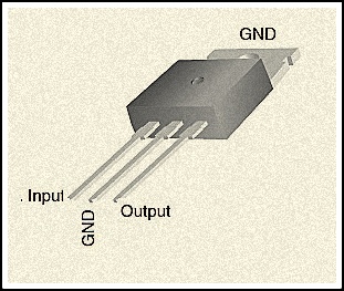
Pin Diagram of IC 7805
The pin explanation of the 7805 is described in the following table:
| In this pin of the IC positive unregulated voltage is given in regulation. | ||
| In this pin where the ground is given. This pin is neutral for equally the input and output. | ||
| The output of the regulated 5V volt is taken out at this pin of the IC regulator. |
In the circuit diagram C2 as well as C3 are filter capacitor while bypass capacitors are the C1 and C4.The electrolytic polarized capacitors are employed for this purpose. For the purpose of filter capacitors normally 10mfd value of the capacitor used. And in these projects we also used 100mfd value of the capacitor. While in all kinds of circuit the value of bypass capacitor is 0.1 mfd. And in generally un-polarized mainly disc capacitors employed for this purpose.
Currently we have the circuit for the 5V DC positive regulation and we are also familiar with the component values used in the circuit. In the table below we have mentioned the value in detail of all the components used in the circuit of 5V DC positive regulator.
Example of 7805 Regulator:
How to Get Constant DC Power Supply from AC?
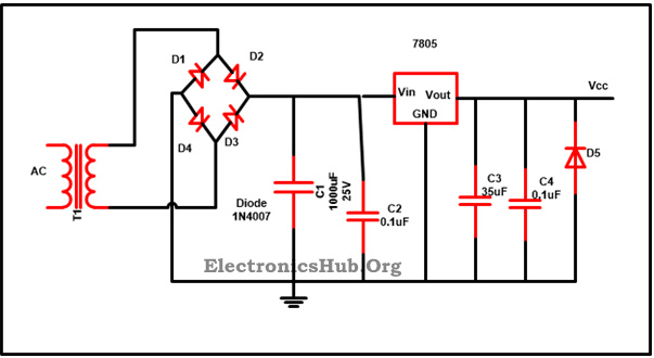
7805 Voltage Regulator Circuit Diagram
Also read the related post: Variable Voltage Power Supply from Fixed Voltage Regulator
The output generated from the unregulated DC output is susceptible to the fluctuations of the input signal.IC voltage regulator is connected with bridge rectifier in series in these project so to steady the DC output against the variations in the input DC voltage.To obtain a stable output of 5V, IC 7805 is attached with 6-0-6V along with 500mA step down transformer as well as with rectifier.To suppress the oscillation which might generate in the regulator IC, C2 capacitor of 0.1 uF value is used. When the power supply filter is far away from the regulated IC capacitor C2 is used.Ripple rejection in the regulator is been improved by C4 capacitor(35uf) by avoiding the ripple voltage to be amplified at the regulator output.The output voltage is strengthen and deduction of the output voltage is done capacitor C3(0.1uF). To avoid the chance of the input get shorted D5 diode is used to save the regulator. If D5 is not presented in the circuit, the output capacitor can leave its charge immediately during low impedance course inside the regulators.
0 comments:
Post a Comment