
Introduction to RTC:
Real time clock also referred as RTC is an important device or integrated circuit which will keep the track of current time. RTC is mainly used in computers, mainframes servers and embedded applications (mobile phone, tablets, organizers, PDA etc).
The main function of the RTC is to keep the track of time of the device even though it is in off or turned off state. The best example is your computer, even though if you shut down your computer for really long time you can see the exact time on your desktop.
Battery is used as external power source and connected to the RTC, to keep the track of the system time even if your computer or embedded system is turned off. If we use lithium battery as external power source RTC will work minimum 3 years even if your system is turned off.
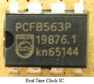
Pin Configuration of PCF8563:
PCF8563 is a RTC and Calendar developed by NXP Semiconductor.PCF8563 uses bidirectional I2C (inter integrated circuit) for interfacing with other peripheral. The bus speed is 400 kbps and incremented automatically after each written or read data byte.
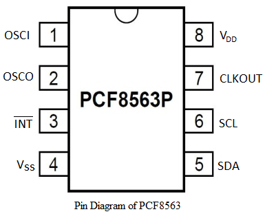
There are 8 pins which are on the IC as seen in the below figure
- OSC1 and OSC0: These two pins connected by the 32.768 kHz crystal oscillator and which provide the source clock for the circuit.
- INT: This pin mainly used to provide an external interrupt to the RTC. For example: in alarm application after the alarm occur it should set back to original state, to set back it to original state the user must give an interrupt to the RTC.
- Vss: Ground
- Vdd: Vdd is the pin where we have to give the supply voltage to the RTC. Battery is connected to the Vdd for uninterrupted power supply, even if the main supply voltage is turned off. The operating voltages are 1V- 5V.
- CLKOUT: for all the application we cannot use 32.768 kHz clock for other application we may need small clock like 32 Hz, 1 Hz for microcontroller clock , input to the charge pump etc.
- SCL and SDA: SCL is serial clock; SDA serial data pins which are mainly used to interface with the other peripherals through I2c (inter integrated circuit). Through these pins only data is exchanged between the other peripherals and RTC. Clock is given to the SCL and Data is given to the SDA.
Functional Features of PCF8563:
- Provides year, month, day, weekday, hours, minutes, and seconds based on a 32.768 kHz quartz crystal.
- Battery backup input pin and switch-over circuit.
- Freely programmable timer and alarm with interrupt capability.
- Selectable integrated oscillator load capacitors for CL = 7 pF or CL = 12.5 pF.
- Internal Power-On Reset (POR).
- Open-drain interrupt or clock output pins.
- Programmable offset register for frequency adjustment.
PIC Microcontroller:
Peripheral Interface controller is developed by general instruments in the year 1975. Hardware architecture and reduced instruction set are used in it. Peripherals like ADC, PWM, OP-AMPS, TIMERS, CAPTURE/COMPARE and DAC etc are inbuilt in PIC microcontroller. Communication protocols like I2C, SPI (serial peripheral Interface) USART (Universal Synchronous Asynchronous Receiver Transmitter), CAN (Control Area Network), ETHERNET are used to communicate with the other external peripheral which are connecter to the PIC micro controller.
PIC is available in different architectural like 8 bit, 16 bit, 32 bit. According to the application we can use the architecture.
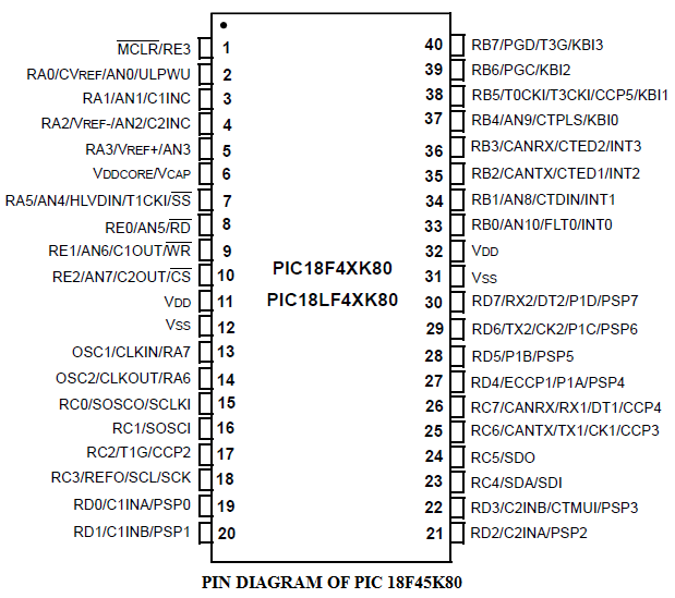
PIC 18F45K80 is a PIC 16 bit microcontroller developed by microchip and it belong to PIC 18F66K80 family. PIC 18F45k80 has 40 pin in PDIP (Plastic Dual Inline Package) and 44 pin in TQFP (Thin Quad Flat Package).
PIC 18F45K80 Features:
- Program memory of 32 Kbytes and data memory of 3648 bytes
- 40-44 pins and 35 I/O pins
- Operating Voltage Range: 1.8V to 5.5V
- On-Chip 3.3V Regulator
- Operating Speed up to 64 MHz
- Up to 64 Kbytes On-Chip Flash Program Memory
- Five CCP/ECCP modules
- Five 8/16-Bit Timer/Counter modules and Two Analog Comparators
- Configurable Reference Clock Output
- Charge Time Measurement Unit (CTMU) and One Master Synchronous Serial Port (I2c and SPI)
- Two Enhanced Addressable USART modules 12-Bit A/D Converter with up to 11 Channels Data Signal Modulator module.
PIN Diagram of PIC Microcontroller:
Interfacing PIC with RTC:
Connect the RTC SDL and SCL pins to the PIC controller pins through the pull up resistor (Pull up resistor is nothing but giving the voltage to the resistors (5k – 10k) to the SDL and SCL wires, here we should give VCC voltage which is 5v). Using the serial interface we can see the output in the terminal.
Circuit Diagram:
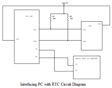
So by seeing the circuit we can easily understand how the connections are given. But care should be taken with the resistance value. The total project can be divided into three steps
- Interfacing PIC18F to RTC.
- Interfacing UART to PIC18F for serial communication purpose to see the RTC output in HyperTerminal of PC.
- Interfacing RTC output to the Serial communication.
NOTE: same circuit and code can be used for PIC 16F and PIC18F series. In the code you have to change the pin configurations only in the initialization functions.
Code for the Project:
#include <htc.h>
#include <pic18F45k80.h>
#include <stdio.h>
#include <pic18F45k80.h>
#include <stdio.h>
#define RTC_ADDR 0xA3
#define RTC_ADDW 0XA2
#define REGBASE_RTC 0x02
#define RTC_ADDW 0XA2
#define REGBASE_RTC 0x02
unsigned char sec,min,hour,day,date,month,year;
unsigned char data[7]={0x00,0x00,0x00,0x00,0x00,0x00,0x00};
unsigned char data[7]={0x00,0x00,0x00,0x00,0x00,0x00,0x00};
int i;
void i2c_init()
{
TRISCbits.TRISC3 = 1; // SCL dir input
TRISCbits.TRISC4 = 1; // SDA dir input
SSPSTATbits.SMP= 1;//I2C slew rate control disabled
SSPCON1= 0x28;//enable i2c master
SSPCON2= 0x00; //master mode
SSPADD = 4;//fosc=400khz,osc=8mhz
PIR1bits.SSPIF=0;// clear interrupt flag
OSCCON=0X70;
TRISCbits.TRISC4 = 1; // SDA dir input
SSPSTATbits.SMP= 1;//I2C slew rate control disabled
SSPCON1= 0x28;//enable i2c master
SSPCON2= 0x00; //master mode
SSPADD = 4;//fosc=400khz,osc=8mhz
PIR1bits.SSPIF=0;// clear interrupt flag
OSCCON=0X70;
}
void i2c_idle()
{
while (( SSPCON2 & 0x1F ) | (SSPSTATbits.R_W));
}
void i2c_start()
{
i2c_idle();
SSPCON2bits.SEN = 1; //Initiates Start condition on SDA and SCL pins. Automatically cleared by hardware.
while (SSPCON2bits.SEN);
SSPCON2bits.SEN = 1; //Initiates Start condition on SDA and SCL pins. Automatically cleared by hardware.
while (SSPCON2bits.SEN);
}
void i2c_stop()
{
SSPCON2bits.PEN = 1; //Initiates Stop condition on SDA and SCL pins. Automatically cleared by hardware.
while(SSPCON2bits.PEN);
i2c_idle();
while(SSPCON2bits.PEN);
i2c_idle();
}
void i2c_restart(void)
{
SSPCON2bits.RSEN = 1;
while(SSPCON2bits.RSEN == 1); //Initiates Repeated Start condition on SDA and SCL pins. Automatically cleared by hardware.
i2c_idle();
while(SSPCON2bits.RSEN == 1); //Initiates Repeated Start condition on SDA and SCL pins. Automatically cleared by hardware.
i2c_idle();
}
unsigned char rtc_read(unsigned char addr)
{
unsigned char x;
i2c_restart();// Enable the repeated Start Condition
SSPBUF= RTC_ADDW; // Slave address + Write command
i2c_idle();
SSPBUF=addr;
//Write the location (memory address of Hour, minute, etc…
i2c_idle ();
i2c_restart(); // Enable the repeated Start Condition
SSPBUF=RTC_ADDR; // Slave address + Read command
i2c_restart ();
SSPCON2bits.RCEN=1; // Enable to receive data
i2c_idle();
SSPCON2bits.ACKDT=1; // Acknowledge the operation (Send NACK)
SSPCON2bits.ACKEN=1; // Acknowledge sequence on SDA & SCL pins
i2c_stop();// Enable the Stop bit
x=SSPBUF;// Store the Receive value in a variable
return (x);
/*
SSPCON2bits.RCEN=1;
while(SSPCON2bits.RCEN);
while(!SSPSTAT.bits.BF);
value=RCREG;
if(ack==1)
{
SSPCON2bits.ACKDT=1;
SSPCON2bits.ACKEN=1;
while(SSPCON2bits.ACKEN);
SSPCON2bits.ACKEN=1;
while(SSPCON2bits.ACKEN);
}
else
{
SSPCON2bits.ACKDT=0;
SSPCON2bits.ACKEN=1;
while(SSPCON2bits.ACKEN);
SSPCON2bits.ACKEN=1;
while(SSPCON2bits.ACKEN);
}
*/
*/
}
void rtc_write (unsigned char data,unsigned char addr)
{
i2c_start();//Initiate Start condition on SDA & SCL pins
i2c_idle();
SSPBUF=RTC_ADDW;// Slave address + Write command
i2c_idle();
SSPBUF=addr;// Write the location
i2c_idle();
SSPBUF=data;// Write the Data
i2c_idle();
i2c_stop(); // Enable the Stop bit
i2c_idle();
i2c_idle();
SSPBUF=RTC_ADDW;// Slave address + Write command
i2c_idle();
SSPBUF=addr;// Write the location
i2c_idle();
SSPBUF=data;// Write the Data
i2c_idle();
i2c_stop(); // Enable the Stop bit
i2c_idle();
}
/*unsigned char x;
i2c_start();
i2c_idle();
SSBUF=RTC_ADDW;
if (SSPCON1bits.WCOL)// Check for write collision
return;
while(SSPSTATbits.BF); // Wait until write cycle is complete
i2c_idle();
i2c_restart();
SSBUF=value;
if (SSPCON1bits.WCOL)// Check for write collision
return;
while(SSPSTATbits.BF); // Wait until write cycle is complete
i2c_idle();
}*/
void uart_init(void)
{
TRISC6=1;
TRISC7=1;
SPBRG1 =0x19;
RCSTA1 =0x90;
TXSTA1 =0x20;
BAUDCON1=0x00;
OSCCON=0x70;
PMD0=0x00;
TRISC7=1;
SPBRG1 =0x19;
RCSTA1 =0x90;
TXSTA1 =0x20;
BAUDCON1=0x00;
OSCCON=0x70;
PMD0=0x00;
}
void byte_out(unsigned char value)
{
TXREG1 = value;
while (TXIF == 0) {;}
TXIF = 0;
return;
while (TXIF == 0) {;}
TXIF = 0;
return;
}
void DelayMs(unsigned int Ms)
{
int delay_cnst;
while(Ms>0)
{
Ms–;
for(delay_cnst = 0;delay_cnst <220;delay_cnst++);
}
while(Ms>0)
{
Ms–;
for(delay_cnst = 0;delay_cnst <220;delay_cnst++);
}
}
void printHexToAscii(unsigned char value)
{
byte_out(((value&0xf0)>>4)+0x30);
byte_out((value&0x0f)+0x30);
/*
for(i=0;i<3;i++)
{
byte_out(data[i]);
}
//UARTSend( 0, data, 5 );
//return &data[0];
*/
byte_out((value&0x0f)+0x30);
/*
for(i=0;i<3;i++)
{
byte_out(data[i]);
}
//UARTSend( 0, data, 5 );
//return &data[0];
*/
}
void main()
{
int count=0;
DelayMs(20);
i2c_init();
uart_init();
for(i=REGBASE_RTC;i<REGBASE_RTC+7;i++)
rtc_write(i,data[i]);
DelayMs(20);
while(1)
{
sec=rtc_read(REGBASE_RTC)&0x7f; // Read second
min=rtc_read(REGBASE_RTC+1)&0x7f; // Read minute
hour=rtc_read(REGBASE_RTC+2)&0x3f; // Read hour
day=rtc_read(REGBASE_RTC+3)&0x3f; // Read day
date=rtc_read(REGBASE_RTC+4)&0x07; // Read date
month=rtc_read(REGBASE_RTC+5)&0x1F;// Read month
year=rtc_read(REGBASE_RTC+6); // Read year
printHexToAscii(hour);
byte_out(‘:’) ;
printHexToAscii(min);
byte_out(‘-‘);
printHexToAscii(sec);
byte_out(‘/’);
printHexToAscii(day);
byte_out(‘\n’);
printHexToAscii(date);
byte_out(‘-‘);
printHexToAscii(month);
byte_out(‘-‘);
printHexToAscii(year);
printf(“Time: %x : %x : %x “,(hour&0x1f),min,sec);//Display the Hours, Minutes, Seconds(hours is taken from 5 LSB bits
printf(“Date: %x / %x / %x \r”,date,month,year);//Display the Date, Month, Year
DelayMs(150);
}
}
0 comments:
Post a Comment