
The main principle of this circuit is to switch ON the light when the LDR is illuminated. The light dependent resistor will have high resistance in darkness and low resistance in the light. The comparator used here has LDR connected to its inverting terminal and potentiometer connected to its non-inverting pin.
When the light falls on the Light Dependent Resistor, the comparator compares the voltages at the reference pin that is with the non-inverting pin and the inverting pin of the op-amp. If the voltage at the non-inverting pin is greater than the voltage at the inverting pin the transistor cannot be switched. If the voltage at non-inverting pin is less than the voltage at the inverting pin, the output of the comparator can switch the transistor.
Thus the relay switches and light are switched on when LDR is illuminated as transistor switches.
Also read the related post: Unambiguous Night Lamp Switch Circuit
Light Activated Switch Circuit Diagram:
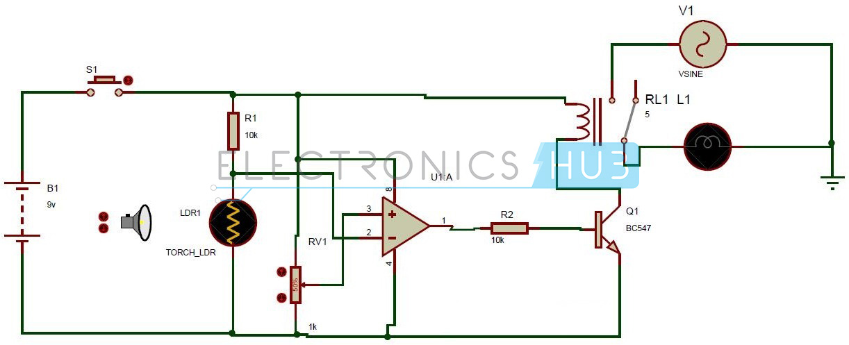
Circuit Diagram of Light Activated Switch
Circuit Components:
- LM358 comparator IC U1.
- Transistor Q1.
- Relay RL1.
- Light Dependent resistor LDR1.
- Resistor R1, R2.
- Potentiometer RV1.
- Bulb L1.
- Battery B1.
Light Activated Switch Circuit Design:
The light activated switch mainly consists of comparator IC LM358.It can have voltages ranging from 3-32 volts. The LM358 IC has internally frequency compensated two operational amplifiers. In the present circuit only one op-amp is used for comparing the input voltages. It has 8pins.In these eight pins pin 1, 2, 3, are used by the first op-amp and 4,8 pins are common for both the op amps. Third pin is the inverting pin whose input is given from the Light Dependent Resistor. Second pin is the non-inverting pin and its input is given from the potentiometer. Eighth pin is connected to the supply voltage and 4th pin is connected to the ground.
Light dependent resistor has high resistance value in darkness as light illumination on the resistor increases resistance value decreases. Here a two mega ohm Light Dependent Resistor is used. It has resistance value ranging from 2000ohms to 2 mega ohms. This is connected to the supply through a resistor of 10k resistance.
Also read the related post: Auto Intensity Control of High Power LEDs
BC547 is an NPN transistor. It has cutoff voltage of 0.7v. NPN transistors are initially open circuited that is when there no base voltage, there is no flow of current from emitter to collector. When the base gets required voltage transistor starts conducting. Here, base is connected to the output of the LM358 IC through a resistor of 10kohms.Emitter is connected to the ground. Collector is connected to the one of the relay pins.
Relay used here is a magnetic relay. It has 5 pins. They are normally open, normally closed, COM, A, B. The A, B are the coil pins. In A, B one is connected to the transistor and the other pin is connected to the supply voltage. Initially, the magnetic switch i.e. COM pin is connected to the normally connected i.e. NC pin. When voltage is applied to the relay COM pin is connected to the normally open pin.
One end of the light is connected to the COM pin of the relay and the other is connected to the ground. Power supply is connected to the normally open pin of the relay.
How to Operate this Light Activated Switch Circuit?
- Initially connect the Ac bulb to the relay in series.
- Now, connect the battery to the circuit.
- Press the button B1.
- Now, adjust the light falling on the Light Dependent Resistor.
- When the torch is away from the LDR light does not glow.
- Move the torch near to the LDR, one can observe the bulb glowing.
- This because the comparator outputs a voltage to switch the transistor and thus relay other end is connected to the ground.
- Finally relay starts switching and the bulb is switched.
Light Activated Switch Circuit Applications:
- This circuit can be used in security applications like when there is darkness on the LDR, it stops lighting.
- This can be used in applications where the light is switched on /off depending on the ambient light
0 comments:
Post a Comment