
n this session we will have brief discussion on how to interface 16×2 LCD module to AT89C51which is a 8051 family microcontroller. We use LCD display for the messages for more interactive way to operate the system or displaying error messages etc. interfacing LCD to microcontroller is very easy if you understanding the working of LCD, in this session I will not only give the information of LCD and also provide the code in C language which is working fine without any errors.
Interfacing 16×2 LCD with 8051 Circuit Diagram:
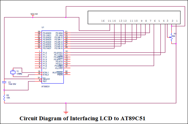
Interfacing LCD to AT89C51:
LCD: 16×2 Liquid Crystal Display which will display the 32 characters at a time in two rows (16 characters in one row). Each character in the display of size 5×7 pixel matrix, Although this matrix differs for different 16×2 LCD modules if you take JHD162A this matrix goes to 5×8. This matrix will not be same for all the 16×2 LCD modules. There are 16 pins in the LCD module, the pin configuration us given below
So by reading the above table you can get a brief idea how to display a character. For displaying a character you should enable the enable pin (pin 6) by giving a pulse of 450ns, after enabling the pin6 you should select the register select pin (pin4) in write mode. To select the register select pin in write mode you have to make this pin high (RS=1), after selecting the register select you have to configure the R/W to write mode that is R/W should be low (R/W=0).
Follow these simple steps for displaying a character or data
- E=1; enable pin should be high
- RS=1; Register select should be high
- R/W=0; Read/Write pin should be low.
To send a command to the LCD just follows these steps:
- E=1; enable pin should be high
- RS=0; Register select should be low
- R/W=1; Read/Write pin should be high.
Commands: There are some preset commands which will do a specific task in the LCD. These commands are very important for displaying data in LCD. The list of commands given below:
To get the detailed information, Click Here and Download the Datasheet
Circuit Explanation:
The crystal oscillator is connected to XTAL1 and XTAL2 which will provide the system clock to the microcontroller the data pins and remaining pins are connected to the microcontroller as shown in the circuit. The potentiometer is used to adjust the contrast of the LCD. You can connect data pins to any port. If you are connecting to port0 then you have to use pull up registers. The enable, R/W and RS pins are should be connected to the 10, 11 and 16 (P3.3, P3.4 and P3.5).
Programming LCD to 8051:
Coming to the programming you should follow these steps:
- STEP1: Initialization of LCD.
- STEP2: Sending command to LCD.
- STEP3: Writing the data to LCD.
Initializing LCD: To initialize LCD to the 8051 the following instruction and commands are to be embed in to the functions
- 0x38 is used for 8-bit data initialization.
- 0xFH for making LCD on and initializing the cursor.
- 0X6H for incrementing the cursor which will help to display another character in the LCD
- 0x1H for clearing the LCD.
Sending Data to the LCD:
- E=1; enable pin should be high
- RS=1; Register select should be high for writing the data
- Placing the data on the data registers
- R/W=0; Read/Write pin should be low for writing the data.
Important Post – Interfacing 7 Segment Display with 8051 Microcontroller
The program given below will use above functions and display the complete string which is given by the programmer to display the data. You have provided two demo codes working properly and easy to understand.
#include <REGX51.H>
#include <string.h>
#include <stdio.h>
#include <string.h>
#include <stdio.h>
sfr LCD=0xa0;
sbit EN=P3^6;
sbit RS=P3^7;
sbit EN=P3^6;
sbit RS=P3^7;
voidnop(void);
void delay_1s(unsigned char t);
voidinitial_lcd(void);
void delay(void);
voidstring_to_lcd(unsigned char *s);
voidwrite_lcd(unsigned char dat,unsignedint com);
void delay_50ms(unsigned char x);
void delay_1s(unsigned char t);
voidinitial_lcd(void);
void delay(void);
voidstring_to_lcd(unsigned char *s);
voidwrite_lcd(unsigned char dat,unsignedint com);
void delay_50ms(unsigned char x);
void main()
{
{
P0=0xff;
P1=0xff;
P3=0xff;
delay_50ms(4);
initial_lcd();
write_lcd(0x80,0);
string_to_lcd(” WELCOME TO “);
write_lcd(0xc0,0);
string_to_lcd(“INNOVATE ENG SOL”);
P1=0xff;
P3=0xff;
delay_50ms(4);
initial_lcd();
write_lcd(0x80,0);
string_to_lcd(” WELCOME TO “);
write_lcd(0xc0,0);
string_to_lcd(“INNOVATE ENG SOL”);
}
voidnop(void)
{
{
unsigned char n;
for(n=0;n<20;n++);
for(n=0;n<20;n++);
}
//………………delay routine……………..//
void delay_1s(unsigned char t)
{
{
unsigned char i,j;
for(i=0;i<t;i++)
for(i=0;i<t;i++)
{
for(j=0;j<20;j++)
{
TMOD=0x01;
TH0=0x3c; //for 12MHz (12/12MHZ)=1u>per cycle operation
TL0=0xb0; //50ms delay get (50m/1u)=50000;
TR0=1; //Load value is =65536-50000=15536(=3cb0H)
TH0=0x3c; //for 12MHz (12/12MHZ)=1u>per cycle operation
TL0=0xb0; //50ms delay get (50m/1u)=50000;
TR0=1; //Load value is =65536-50000=15536(=3cb0H)
while(TF0!=1); //wait for overflow flag
TF0=0;
TF0=0;
}
}
}
voidinitial_lcd(void)
{
{
write_lcd(0x38,0);
write_lcd(0x0c,0);
write_lcd(0x01,0);
write_lcd(0x0c,0);
write_lcd(0x01,0);
}
voidwrite_lcd(unsigned char dat,unsignedint com)
{
{
RS=com;
LCD=dat;nop();
EN=1;nop();
EN=0;
nop();
LCD=dat;nop();
EN=1;nop();
EN=0;
nop();
}
voidstring_to_lcd(unsigned char *s)
{
unsigned char i,l;
l=strlen(s);
for(i=0;i<l;i++)
l=strlen(s);
for(i=0;i<l;i++)
{
write_lcd(*s,1);delay_50ms(1);
s++;
s++;
}
}
void delay_50ms(unsigned char x)
{
{
unsigned char i;
for(i=0;i<x;i++)
for(i=0;i<x;i++)
{
TMOD=0x01;
TH0=0x3c;
TL0=0xb0;
TR0=1;
while(!TF0);
TF0=0;
TR0=0;
TH0=0x3c;
TL0=0xb0;
TR0=1;
while(!TF0);
TF0=0;
TR0=0;
}
}
******************************** SECOND DEMO CODE*****************************
#include<reg51.h>
#define cmdport P3
#define dataport P2
#define q 100
#define cmdport P3
#define dataport P2
#define q 100
sbitrs = cmdport^0; //register select pin
sbitrw = cmdport^1; //read write pin
sbit e = cmdport^6; //enable pin
sbitrw = cmdport^1; //read write pin
sbit e = cmdport^6; //enable pin
void delay(unsigned intmsec) //Function to provide time delay in msec.
{
inti,j ;
for(i=0;i<msec;i++)
for(j=0;j<1275;j++);
for(i=0;i<msec;i++)
for(j=0;j<1275;j++);
}
voidlcdcmd(unsigned char item) //Function to send command to LCD
{
dataport = item;
rs= 0;
rw=0;
e=1;
delay(1);
e=0;
rs= 0;
rw=0;
e=1;
delay(1);
e=0;
}
voidlcddata(unsigned char item) //Function to send data to LCD
{
dataport = item;
rs= 1;
rw=0;
e=1;
delay(1);
e=0;
rs= 1;
rw=0;
e=1;
delay(1);
e=0;
}
void main()
{
lcdcmd(0x38); //for using 8-bit 2 row mode of LCD
delay(100);
lcdcmd(0x0E); //turn display ON for cursor blinking
delay(100);
lcdcmd(0x01); //clear screen
delay(100);
lcdcmd(0x06); //display ON
delay(100);
lcdcmd(0x86); //bring cursor to position 6 of line 1
delay(100);
lcddata(‘A’);
delay(100);
lcdcmd(0x0E); //turn display ON for cursor blinking
delay(100);
lcdcmd(0x01); //clear screen
delay(100);
lcdcmd(0x06); //display ON
delay(100);
lcdcmd(0x86); //bring cursor to position 6 of line 1
delay(100);
lcddata(‘A’);
0 comments:
Post a Comment