
Have you ever tried to design a battery charger which charges the battery automatically when battery voltage is below the specified voltage? This article explains you how to design an automatic battery charger. This charger automatically shut off the charging process when battery attains full charge. This prevents the deep charge of the battery. If the battery voltage is below the 12V, then circuit automatically charges the battery.
Automatic Battery Charger Circuit Principle:
If the battery voltage is below 12V, then the current from LM317 IC flows through the resistor R5 and diode D5 to the battery. At this time zener diode D6 will not conduct because battery takes all the current for charging.
When the battery voltage rises to 13.5V, the current flow to the battery stops and zener diode gets the sufficient breakdown voltage and it allows the current through it. Now the base of the transistor gets the sufficient current to turn on so that the output current from LM317 voltage regulator is grounded through the transistor Q1. As a result Red LED indicates the full of charge.
Also get an idea about how to design a battery charger circuit using SCR
Automatic 12v Portable Battery Charger Circuit Diagram:
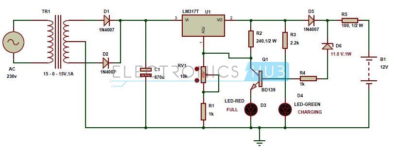
Circuit Diagram of Automatic Battery Charger
Circuit Components:
- 15-0-15V, 1A center tapped transformer
- LM317T voltage regulator
- 12V DC battery
- BD139 NPN transistor
- LED’s – red, green
- 8.2V zener diode
- 1n4007 diodes – 3
- electrolytic capacitor – 470uF
- pot – 10k
- resistors (1/2 watt) – 100, 240 ohms
- 2 Resistors – 1k
- Resistor – 2.2k
- connecting wires
Automatic Battery Charger Circuit Design:
This automatic battery charger circuit design mainly involves two sections – power supply section and load comparison section.
The main supply voltage 230V, 50Hz is connected to the primary winding of the center tapped transformer to step down the voltage to 15-0-15V.
The output of the transformer is connected to the Diodes D1, D2. Here diodes D1, D2 are used to convert low AC voltage to pulsating DC voltage. This process is also called as rectification. The pulsating DC voltage is applied to the 470uF capacitor to remove the AC ripples. Thus the output of the capacitor unregulated Dc voltage. This unregulated DC voltage is now applied to the LM317 variable voltage regulator to provide regulated DC voltage. The output voltage of this voltage regulator is variable from 1.2V to 37V and the maximum output current from this IC is 1.5A. The output voltage of this voltage regulator is varied by varying the pot 10k which is connected to the adjust pin of LM317.
Lm317 voltage regulator output is applied to the battery through the diode D5 and resistor R5. Here diode D5 is used to avoid the discharge of battery when main supply fails. When battery charges fully, the zener diode D6 which connected in reverse bias conducts. Now base of BD139 NPN transistor gets the current through the zener so that the total current is grounded. In this circuit green LED is used for indicating the charge of the battery. Resistor R3 is used to protect the green LED from high voltages.
Charger settings:
The output voltage of the battery charger should be less than 1.5 times of the battery and the current of the charger should be 10% of the battery current. Battery charger should have over voltage protection, short circuit protection and reversed polarity protection.
NOTE: Also get an idea about how to build a battery charging level indicator circuit?
How to Operate this Automatic Battery Charger Circuit?
- Initially give the connection as shown in the circuit diagram.
- While giving the connections, take care of connections in such a way that there is no common connection between AC and DC supplies.
- Now connect a fully charged battery as a load to the circuit, then red LED glows to indicate that the battery is full and charger can be left unattended.
- Connect discharged battery as a load, now you can observe that green LED will glow to indicate that battery is charging.
- Switch off the main supply.
Automatic Battery Charger Circuit Advantages:
- The battery charger circuit is simple and cost effective.
- Over voltage and current protection.
- Over temperature protection.
- The system is easily portable.
- Automatically charges the battery and stops charging when battery is fully charged.
- Avoids battery discharge when power failed.
Automatic Battery Charger Applications:
- This automatic battery charger is used to charge 12V Lead-acid batteries. (Related Post– Lead Acid Battery Charger using LM317)
- Used to charge car batteries since IC output voltage is variable.
- Used to charge toy auto mobile batteries with a little modification.
Limitations of this Circuit:
- It takes long time for charging the battery
- This circuit is tested in simulation software and may require some practical changes.
Thank you so much Roshini for your valuable feedback.. :) ...Its encouraging me a lot...
ReplyDeleteyou can share your thoughts here and you can contact @
mindsforest@gmail.com
Thanks for this great post, i find it very interesting and very well thought out and put together. I look forward to reading your work in the future. auto sliding gate bd
ReplyDelete"Makes whipped cream in seconds!" Nosboss
ReplyDelete