
When we talk about controlling the robot, the first thing comes into the mind is controlling DC motors. Interfacing DC motor to the microcontroller is very important concept in Robotic applications. By interfacing DC motor to the microcontroller, we can do many things like controlling the direction of the motor, controlling the speed of the motor. This article describes you how to control the DC motor using AT89C51 controller.
Interfacing DC Motor to 8051 Circuit Principle:
The maximum output current of microcontroller pin is 15mA at 5V. But the power requirements of most of DC motors is out of reach of the microcontroller and even the back emf (electro motive force) which is produced by the motor may damage the microcontroller. Hence it is not good to interface DC motor directly to the controller. So use motor driver circuit in between of DC motor and controller.
Also read the interesting concept: Interfacing 7 Segment Display to 8051 Microcontroller
Here, we are using L293D motor driver IC to drive DC motors. Using this IC, we can drive 2 DC motors at a time. For this IC motor supply is variable 4.5 to 36V and it provides maximum current of 600mA.
Circuit Diagram of Interfacing DC motor to 8051 Microcontroller:
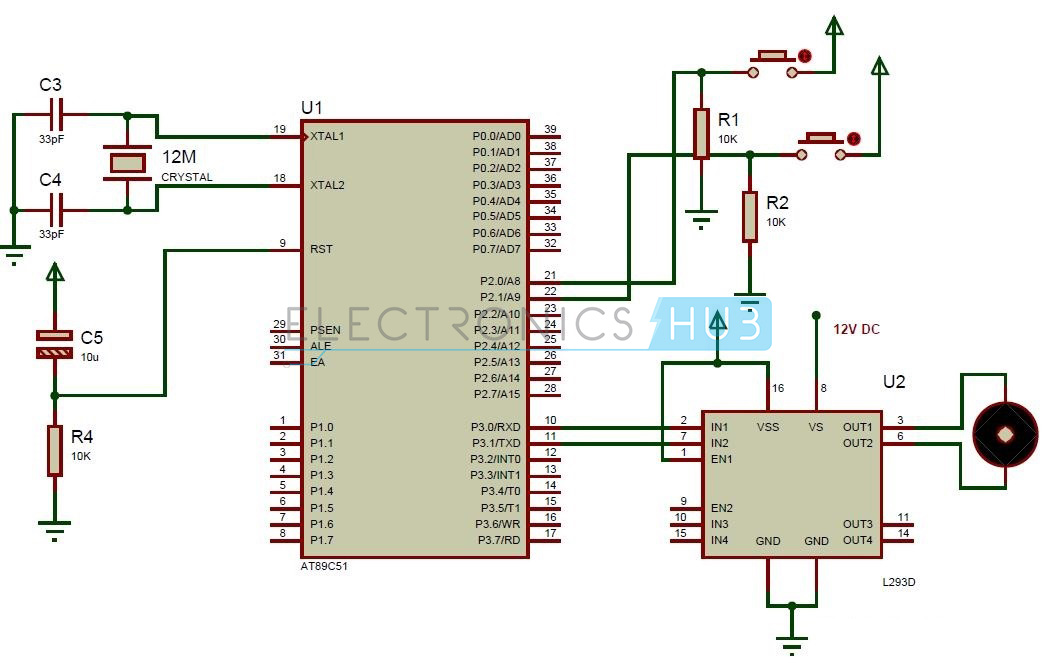
Circuit Diagram of Interfacing DC motor to 8051 Microcontroller
Circuit Components:
- at89c51 microcontroller
- PCB board
- programming cable
- 12V DC battery or Adaptor
- L293D motor driver
- DC motor
- Electrolytic capacitor – 10uF
- 2 Ceramic capacitors – 33pF
- 10k resistors (1/4 watt) – 3
- push buttons – 2
- Connecting sires.
Interfacing DC Motor to 8051 Circuit Design:
The major components in the above circuit diagram are at89c51 microcontroller and motor driver. Here the motor driver input pins IN1, IN2 are connected to the P3.0 and P3.1 respectively to control the motor directions. DC motor is connected to output terminals of L293D. EN1 pin is connected to the 5V DC to drive the motor. Switches are connected to the P2.0 and P2.1 in pull down configuration. First switch rotates the motor in clockwise direction and second switch rotates the motor in anti clockwise direction. 8th pin of motor driver is connected to the battery directly.
L293D Motor Driver:
L293D is a quadruple H- bridge motor driver, as the name suggests it used to drive the DC motors. This IC works based on the concept of H- Bridge. H-bridge is a circuit which allows the voltage in either direction to control the motor direction.
There are 4 input pins for L293D. Motors directions depends on the logic inputs applied at this pins. EN1 and EN2 must be high to drive the 2 DC motors.
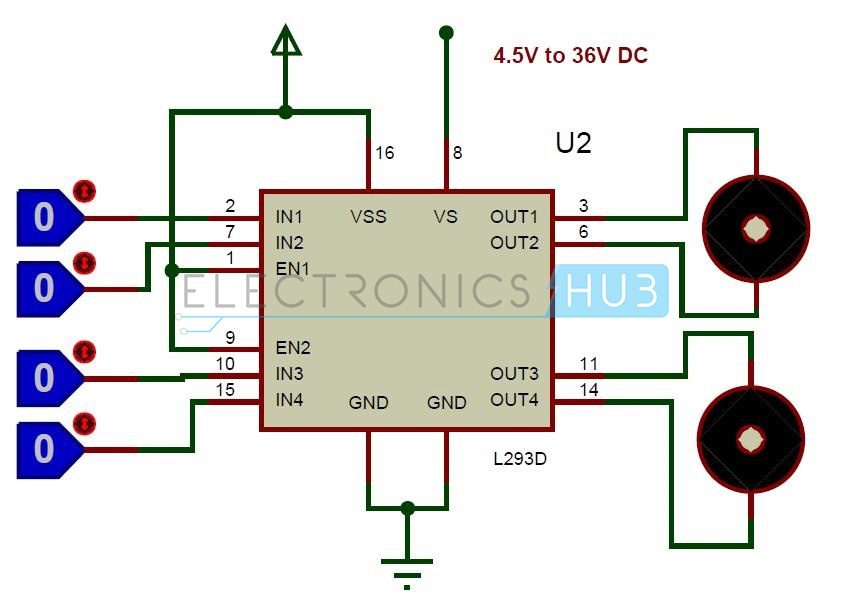
L293D Circuit
- IN1=0 and IN2=0 -> Motor1 idle
- IN1=0 and IN2=1 -> Motor1 Anti-clock wise direction
- IN1=1 and IN2=0 -> Motor1 Clock wise direction
- IN1=1 and IN2=1 -> Motor1 idle
- IN3=0 and IN4=0 -> Motor2 idle
- IN3=0 and IN4=1 -> Motor2 Anti-clock wise direction
- IN3=1 and IN4=0 -> Motor2 Clock wise direction
- IN3=1 and IN4=1 -> Motor2 idle
Algorithm for Interfacing DC Motor to 8051:
- Declare P2.0 and P2.2 as inputs and P3.0 and P3.1 as outputs.
- Now check weather the first button is pressed or not. If pressed, then send logic one to P3.0.
- Next check whether the second button is pressed or not. If pressed, then send logic 1 to P3.1 otherwise send 0 to port 2.
DOWNLOAD PROJECT CODE
How to Operate the Circuit Interfacing DC Motor to 8051?
- Burn the program to the 8051 microcontroller.
- Now give the connections as per the circuit diagram.
- While giving the connections, make sure that there is no direct supply connection from battery to the controller.
- Switch on the board supply, now the motor is at stationary condition.
- Press first button, you can observe that motor will rotate in clockwise direction.
- Press the second button, now the motor rotates in anticlockwise direction.
- Switch off the board supply.
Interfacing DC Motor to 8051 Applications:
- This concept is used in robots to control the robot directions.
- Used to control the speed of the DC motor.
- It is used in the applications where we need to drive the high voltage motors.
0 comments:
Post a Comment