
We usually turn ON the lights in our houses and offices manually. We need to turn ON the lights only when it is dark. So, how will that be if we make a circuit which turns ON the lights automatically when it is dark? In this circuit, we shall see how to make a circuit which turns ON our domestic lights automatically when it is dark.
While making a Night Lamp Switcher, there are many aspects which needs to be taken into consideration without which there is a possibility of destroying the home appliances and lights. In this circuit, strict measures are taken to ensure that the lights to be operated are not damaged because of switching. In general, if we make a simple automatic night lamp switcher, it may turn ON the lights when it is dark. But here comes a problem. When the level of darkness is approaching, the circuit may get successive signals of dark and light with little time intervals. This may cause the circuit to repeatedly turn ON and OFF the lights at a high frequency which can possibly damage our lights within a few minutes or hours. This happens every time at evening as well as in the morning when the light intensity crosses a value for which our circuit is sensitive and toggles the switch.
In this circuit, it is not only a simple automatic light switching circuit, but also that it avoids repeated frequent switching of the devices which is usually ignored in most similar circuits but may have a detrimental effect on our operating devices. In this case, the lights. This is why the circuit is named as intelligent unambiguous night lamp as it intelligently switches the lights by avoiding repeated switching caused by unambiguity.
Related Post – How a Light Activated Switch Circuit Works?
Circuit Diagram for Unambiguous Night Lamp Switcher:
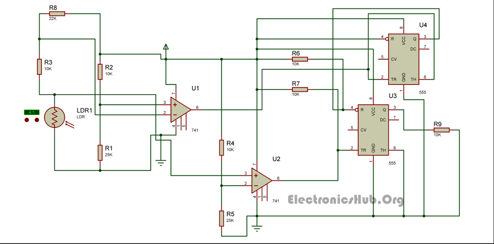
Unambiguous Night Lamp Switch Circuit Diagram
How to Operate this Night Lamp Switcher Circuit?
The circuit has two photo sensing devices which detect two levels of intensities. Light Dependant Resistors are used as photosensitive devices in this circuit. The light dependent resistor used with an op-amp as comparator detects the level of light intensity. The U1 IC 741 produces an output which is the first light intensity and the U2 IC741 detects the second light intensity. These two light intensities are used to calculate when the lights should be On and when they should be Off without producing unambiguous signals.
The two light detecting modules are arranged in such a way that when the first light intensity (dark point 1) is detected, the circuit turns On the relay and hence the lights will turn On. The circuit will turn Off the relay back again when both the light detecting modules detect light. This makes it eliminate ambiguities. There may be simpler circuits which detect darkness and turn On the lights but most of them fail to eliminate undesired repetitive switching. This circuit does a wonderful job by eliminating undesired switching effects.
The 555 IC U3 is in the bistable mode whereas the IC U4 acts as a buffer. The output of first IC 741 is given to the reset pin of the bistable IC whereas the output of second light detecting module with IC 741 is given to the set input of the bistable multivibrator.
Note: Also Read the Post – Automatic Washroom Light Switch
0 comments:
Post a Comment