
This circuit is designed to alert the user when an intruder enters into the home. If there is any obstacle in front of IR sensor, it generates an interrupt signal. This interrupt signal is given to the speaker to alert the user.
Super Sensitive Intruder Alarm Circuit Principle:
IR transmitter always emits the IR (Infrared) rays which have to be received by IR receiver. When there is an obstacle in front of IR sensor, the transmitted IR rays are reflected back to the IR receiver. The output of Op-Amp is high when IR receiver receives the reflected IR rays. This output of operational amplifier is connected to the RESET pin of 555 timer.
Related Post: Security Alarm Circuit without using 555 Timer IC
The output of 555 timer is low when input voltage applied at pin 4 of 555 timer is low.
When input voltage at pin 4 is high, then 555 timer produces the frequency which can be adjusted by the different value combinations of resistors R1, R2 and capacitor C3.
- Obstacle Present → IR Receiver Receives IR Rays → Op-amp Output High → 555 RST Pin High → Speaker Produces the Sound.
- No Obstacle → IR Receiver does not Receive the Rays → Op-amp Output Low → RST Pin Low → No Sound
The output of NE555 is filtered by the 1uF capacitor and fed to the speaker.
Many IR sensors are arranged in house at different locations. The outputs of all these sensors are given to RESET pin of common 555 timer. When any sensor detects the intruder, the reset pin of 555 timer becomes high and speaker will produce the sound.
Super Sensitive Intruder Alarm Circuit Diagram:
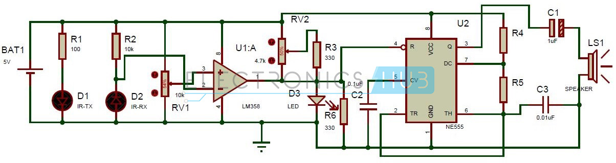
Super Sensitive Intruder Alarm Circuit Diagram
Circuit Components:
- NE555 timer
- LM358 op-amp
- Pot – 10k, 4.7k
- IR transmitter
- IR receiver
- Red led
- Ceramic capacitors – 0.1uF, 0.01uF
- Electrolytic capacitor – 1uF, 16v
- Resistors – 10k, 100, R4,R5
- 2 resistors – 330 ohm
- Speaker
- Battery
Super Sensitive Intruder Alarm Circuit Design:
555 Timer: Here 555 timer acts as a free running oscillator. It will generate the frequency when high pulse is applied at RESET pin. The generated frequency of 555 timer varied by varying resistor values R4, R5 or by varying the capacitor value C3.
Here Pin 2 and pin 6 of 555 timer are shorted to allow the triggering after every timing cycle. In this circuit, capacitor C3 charges through the resistors R4, R5 and discharges through the resistor R5.
LM358 Op-Amp:
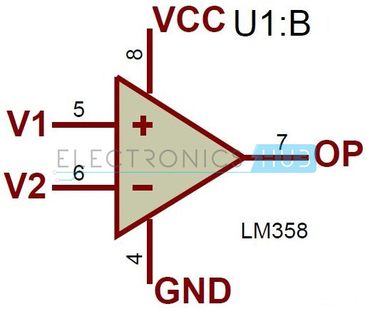
LM358 Op-Amp
IF V1>V2 then OP = HIGH
IF V2>V1 then OP = LOW
LM358 IC consists of two operational amplifiers. Each Op- amp has two inputs (inverting and non – inverting) and one output. The op – amp output is high when non-inverting voltage is greater than the inverting voltage and it is low when inverting voltage is greater than non inverting voltage.
IR Transmitter: The operating voltage of transmitter is around 2 to 3V, to drop the remaining voltage we connect a resistor in series with IR led.
IR Receiver: It is always used in reverse bias. It almost acts as a closed circuit when it receives IR rays and it has high resistance when it does not receive any IR rays.
Also read the post – Motion Detector Circuit using NE555 Timer
How to Operate Super Sensitive Intruder Alarm Circuit?
- Give the connections according to the circuit diagram.
- Connect 5V supply to the circuit.
- Now place the obstacle in front of IR sensor then speaker produces the sound.
- Remove the obstacle now you will not get any sound.
- Disconnect the battery from the circuit.
Super Sensitive Intruder Alarm Circuit Applications:
- This circuit is used in homes and offices for security purpose.
Circuit Limitations:
- This circuit produces the sound even if there is any non-living thing in front of IR sensor.
0 comments:
Post a Comment