
A GPS module is a device that uses
Global Positioning System to determine the location of a vehicle or
person. GPS receivers are used to provide reliable navigation,
positioning and timing services to the users at anytime and anywhere on
the earth. This Global positioning system uses 24 to 32 satellites to
provide the data to the receivers. GPS has become very important for
worldwide navigation and it is useful for land surveying, way marking,
map-making, tracking and surveillance commerce and scientific uses. But,
before going to know about this circuit, get an idea about how to interface LCD with 8051 Microcontroller.

Circuit Components:
The GPS receiver continuously transmits the data as per the NMEA standards using RS232 protocol. In this NMEA format, the LATITUDE and LONGITUDE values of location are available in GPRMC sentence. In this project LATITUDE and LONGITUDE values are extracted from NMEA format and displayed on LCD.
We have to receive the data to the controller form GPS module serially using UART protocol and now extract the latitude and longitude values from the received messages and display them on LCD.
Extraction of Latitude and Longitude values from NMEA Format:
The first received 6 characters from GPS module are compared with string $GPRMC, if matched then will go for further process otherwise repeat the same process again. If string is matched then wait till you will get two 2 commas, next character indicates weather the GPS is activated or not. If this character is A then GPS is activated otherwise GPS is not activated. Now again wait till you get comma (,). The next 9 characters indicate the LATITUDE. Wait till you get 2 more commas (,) the next 10 characters indicates the LONGITUDE.
If you want to check the latitude and longitude values of the location without any coding, then use Trimble studio software. This software directly provides latitude, longitude, altitude, speed, time and date when you interface GPS module. Even it provides your location in Google maps.
The below function is used to extract the LATITUDE and LONGITUDE values from the NMEA format.
void gps ()
{
unsigned int LAT[9], LON[10];
unsigned char Temp, i;
if (rx_data() == ‘$’)
{
if( rx_data() == ‘G’)
{
if (rx_data() == ‘P’)
{
if (rx_data() == ‘R’)
{
if (rx_data() == ‘M’)
{
if (rx_data() == ‘C’)
{
while (rx_data() != ‘,’);
while (rx_data() != ‘,’);
/*checking for “A” condition*/
Temp = rx_data();
if (Temp == ‘A’||Temp == ‘V’)
{
while (rx_data() != ‘,’);
/*latitude values*/
LCDCmd (0x80);
for (i=0; i<9; i++)
{
LAT[i] = rx_data();
LCDData (LAT[i]);
}
while (rx_data() != ‘,’);
while (rx_data() != ‘,’);
/*longitude values*/
LCDCmd (0xc0);
for (i=0; i<10; i++)
{
LON[i] = rx_data();
LCDData (LON[i]);
}
}
}}}}}}
}
Interfacing GPS with 8051 Microcontroller Circuit Principle:
GPS module calculates the position by reading the signals that are transmitted by the satellites. Each satellite transmits the messages continuously which contains time was sent. GPS receiver measures the distance to each satellite based on the arrival time of each message. This information is used to calculate the position of the GPS receiver. The received raw data is converted for the user as LATITUDE, LONGITUDE, ALTITUDE, SPEED and TIME.Interfacing GPS with 8051 Microcontroller Circuit Diagram:
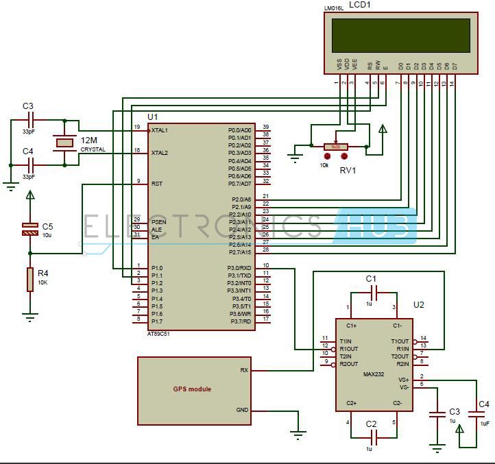
Circuit Diagram of Interfacing GPS to 8051 Microcontroller
- at89c51 controller
- Programming board
- programming cable
- 12V DC battery or adaptor
- max232 IC
- 16*2 LCD
- GPS module
- Pot 10k
- 12 MHz crystal
- Electrolytic capacitors – 1uF (4), 10u
- Ceramic capacitors – 33pF (2)
- Resistor – 10k
Interfacing GPS with 8051 Circuit Design:
In the above circuit, LCD (Liquid crystal display) data pins are connected to PORT2 of the controller and control pins RS, RW and EN are connected to the P1.0, P1.1 and P1.2 respectively. The latitude and longitude values of the location are displayed on LCD. Here pot RV1 is used to adjust the contrast of LCD. The receiver pin of GPS module is connected to the 13th pin of max232 IC and GND pin is connected to ground. Controller RXD pin is connected to the 12th pin of max232. Here max232 IC is used for level conversion.The GPS receiver continuously transmits the data as per the NMEA standards using RS232 protocol. In this NMEA format, the LATITUDE and LONGITUDE values of location are available in GPRMC sentence. In this project LATITUDE and LONGITUDE values are extracted from NMEA format and displayed on LCD.
We have to receive the data to the controller form GPS module serially using UART protocol and now extract the latitude and longitude values from the received messages and display them on LCD.
Extraction of Latitude and Longitude values from NMEA Format:
The first received 6 characters from GPS module are compared with string $GPRMC, if matched then will go for further process otherwise repeat the same process again. If string is matched then wait till you will get two 2 commas, next character indicates weather the GPS is activated or not. If this character is A then GPS is activated otherwise GPS is not activated. Now again wait till you get comma (,). The next 9 characters indicate the LATITUDE. Wait till you get 2 more commas (,) the next 10 characters indicates the LONGITUDE.
If you want to check the latitude and longitude values of the location without any coding, then use Trimble studio software. This software directly provides latitude, longitude, altitude, speed, time and date when you interface GPS module. Even it provides your location in Google maps.
The below function is used to extract the LATITUDE and LONGITUDE values from the NMEA format.
void gps ()
{
unsigned int LAT[9], LON[10];
unsigned char Temp, i;
if (rx_data() == ‘$’)
{
if( rx_data() == ‘G’)
{
if (rx_data() == ‘P’)
{
if (rx_data() == ‘R’)
{
if (rx_data() == ‘M’)
{
if (rx_data() == ‘C’)
{
while (rx_data() != ‘,’);
while (rx_data() != ‘,’);
/*checking for “A” condition*/
Temp = rx_data();
if (Temp == ‘A’||Temp == ‘V’)
{
while (rx_data() != ‘,’);
/*latitude values*/
LCDCmd (0x80);
for (i=0; i<9; i++)
{
LAT[i] = rx_data();
LCDData (LAT[i]);
}
while (rx_data() != ‘,’);
while (rx_data() != ‘,’);
/*longitude values*/
LCDCmd (0xc0);
for (i=0; i<10; i++)
{
LON[i] = rx_data();
LCDData (LON[i]);
}
}
}}}}}}
}
How to Operate Interfacing GPS with 8051 Circuit:
- Initially burn the program to the 8051 microcontroller
- Now give the connections as per the circuit diagram
- Give the supply to the GPS module using adaptor
- Interface GPS module to the computer and open hyper terminal to check the received messages.
- Check whether the GPS is activating or not.
- Now connect the GPS to the circuit, you can observe that LCD displays latitude and longitude values.
- Switch off both the circuit and GPS module supplies.
Interfacing GPS with 8051 Circuit Applications:
- This system is used in marine navigation, car navigation and fleet management
- Used in tracking devices and mapping devices
- Used in personal positioning
- This project is used in embedded system applications to find out the location.
0 comments:
Post a Comment