
Generally, electronic devices produce
more heat. So this heat should be reduced in order to protect the
device. There are many ways to reduce this heat. One way is to switch on
the fan spontaneously. This article describes a circuit that
automatically, switches the fan when it detects the temperature inside
the device greater than its threshold value.
The microcontroller continuously reads temperature from its surroundings. The temperature sensor acts as a transducer and converts the sensed temperature to electrical value. This is analog value which is applied to the ADC pin of the microcontroller. The ATmega8 microcontroller has six multiplexed ADC channels with 10 bit resolution. The analog value is applied to one of the input ADC pins. Thus conversion occurs internally using successive approximation method. For ADC conversion, internal registers should be declared. The ADC pin outputs a digital value. This is compared with the threshold value by the controller which switches the fan if value is greater than threshold.
1) Initially, select the reference voltage to the ADC using ADCMUX register.
2) Select REFS0 and REFS1 values in ADMUX register to set the reference voltage.
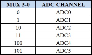
3) Now select the ADC channel using MUX0-MUX3 bits in ADMUX register. Below given table shows the binary value to be placed in the MUX0-MUX3 bits to select a channel.

4) If the sensor is connected to ADC0 channel with AVCC with external capacitor at AREF pin, then the binary value to be assigned to the ADMUX register is ADMUX=0b01000000.
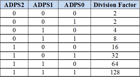
5) Now select the pre scalar value using ADPS0, ADPS1 and ADPS2 bits of ADCSRA register and also enable ADC using ADEN bit in ADSCRA register.
The following bits decide the division factor between XTAL frequency and input clock of ADC:

6) Now enable start conversion bit that is ADCSC in ADCSRA register.
7) After the conversion of the value, an interrupt bit is enabled by the hardware
8) Wait until interrupt bit ADIF is set to 1.
9) The result is stored in two data register of ADC that is ADCL and ADCH. Now read the digital value from these registers

Port B of the microcontroller is connected to the motors through a motor driver IC i.e. L293D. Input pins of the motor driver are connected to the microcontroller. PB0 and PB1 are connected to the input 3 and input 4 of the motor driver IC. PB2 and PB3 pins are connected to the input1 and input2 of the motor driver IC. Output pins are connected to the motor. As the motor has two pins, these are connected to the output pins of the driver IC.
Temperature Controlled DC Fan Circuit Principle:
The main principle of the circuit is to switch on the fan connected to DC motor when the temperature is greater than a threshold value.The microcontroller continuously reads temperature from its surroundings. The temperature sensor acts as a transducer and converts the sensed temperature to electrical value. This is analog value which is applied to the ADC pin of the microcontroller. The ATmega8 microcontroller has six multiplexed ADC channels with 10 bit resolution. The analog value is applied to one of the input ADC pins. Thus conversion occurs internally using successive approximation method. For ADC conversion, internal registers should be declared. The ADC pin outputs a digital value. This is compared with the threshold value by the controller which switches the fan if value is greater than threshold.
Do you know about The Working of Stepper Motor Control Circuit using 8051 Microcontroller?
Declaring of internal ADC Registers:
The ATmega8 microcontroller internally has three register namely ADMUX, ADCSRA, ADC data registers. Analog to digital converter is of 10 bit resolution.1) Initially, select the reference voltage to the ADC using ADCMUX register.
2) Select REFS0 and REFS1 values in ADMUX register to set the reference voltage.
3) Now select the ADC channel using MUX0-MUX3 bits in ADMUX register. Below given table shows the binary value to be placed in the MUX0-MUX3 bits to select a channel.
4) If the sensor is connected to ADC0 channel with AVCC with external capacitor at AREF pin, then the binary value to be assigned to the ADMUX register is ADMUX=0b01000000.
5) Now select the pre scalar value using ADPS0, ADPS1 and ADPS2 bits of ADCSRA register and also enable ADC using ADEN bit in ADSCRA register.
The following bits decide the division factor between XTAL frequency and input clock of ADC:
6) Now enable start conversion bit that is ADCSC in ADCSRA register.
7) After the conversion of the value, an interrupt bit is enabled by the hardware
8) Wait until interrupt bit ADIF is set to 1.
9) The result is stored in two data register of ADC that is ADCL and ADCH. Now read the digital value from these registers
Circuit Diagram of Temperature Controlled DC Fan using Microcontroller:
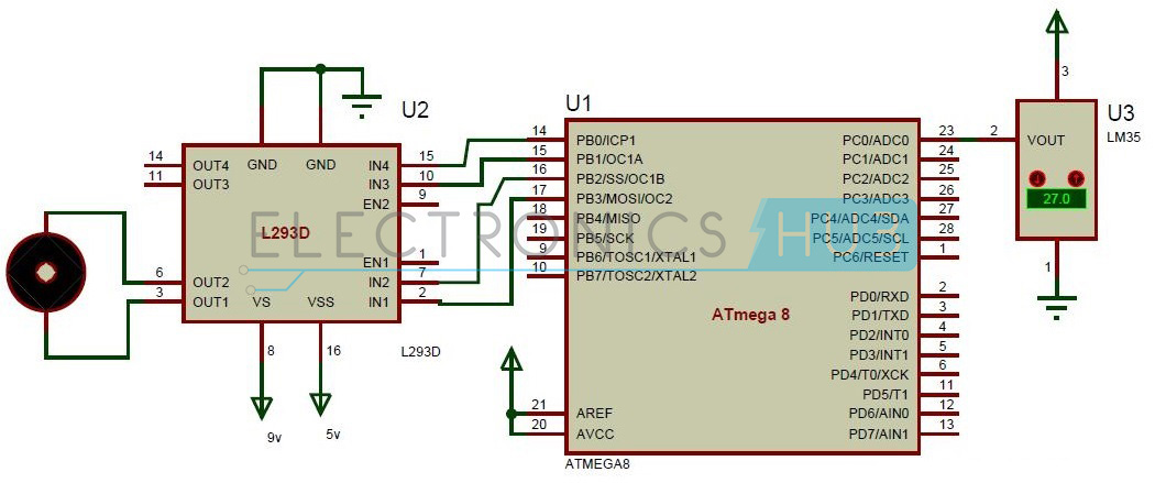
Temperature Controlled DC Fan using ATmega8 Microcontroller Circuit Diagram
Temperature Controlled DC Fan Circuit Design:
The circuit mainly consists of ATmega8 microcontroller, temperature sensor, DC motor, driver IC. Temperature sensor is connected to the input of the ADC pin i.e. ADC0 pin of the microcontroller. Temperature sensor has three input pins, VCC, ground. Middle one is output and the other two pins are ground and VCC. VREF and AVCC for the ADC are applied externally to the microcontroller. Pin 20 and 21 are AREF and AVCC pins connected to the supply voltage of 5v.Port B of the microcontroller is connected to the motors through a motor driver IC i.e. L293D. Input pins of the motor driver are connected to the microcontroller. PB0 and PB1 are connected to the input 3 and input 4 of the motor driver IC. PB2 and PB3 pins are connected to the input1 and input2 of the motor driver IC. Output pins are connected to the motor. As the motor has two pins, these are connected to the output pins of the driver IC.
DOWNLOAD PROJECT CODE
How Temperature Controlled DC Fan Circuit Works using Microcontroller?
- Initially switch the power supply.
- Microcontroller starts reading the temperature of the surroundings.
- The analog value of temperature is given by the temperature sensor.
- This analog value is applied to the analog to digital converter pin of the micro controller.
- This analog value is converted to the digital value by the microcontroller using successive approximation method internally.
- When the temperature is greater than the threshold value, microcontroller sends a command to the controller to switch the motor.
- Thus fan starts rotating.
Temperature Controlled DC Fan Circuit Applications:
- This can be used in home applications.
- The circuit can be used in CPU to reduce the heat.
Hawkscode is an one of the leading IT service providing company from India. That plays with the technology.
ReplyDelete