
We use DC fans in many systems in our
day to day life. For example, CPU fans, fume extinguishers and many more
appliances which we make use of are operated by DC. Most of the times
we will have a need to adjust the speed of the motors to our
requirement. Although some systems have an automatic adjustment system
for fan speed, not all systems possess this functionality. So, we will
have to adjust the speed of our fan ourselves occasionally.
To adjust the speed of our fan manually,
there are multiple ways to do that. We can adjust the speed by using a
resistance in series with the motor. This is the simplest of all ways
but it is not usually preferred because if we want to use any devices
like microcontrollers or any other digital equipment for automating our
DC fan speed, then this method will not work in general. A more
efficient way to proceed is by using pulse width modulation technique to
manage the speed of our DC motor.
Also Read the Related Post – Stepper Motor Controller using AT89C51 Microcontroller
Also Read the Related Post – Stepper Motor Controller using AT89C51 Microcontroller
Circuit Diagram of PWM Based DC Fan Controller:
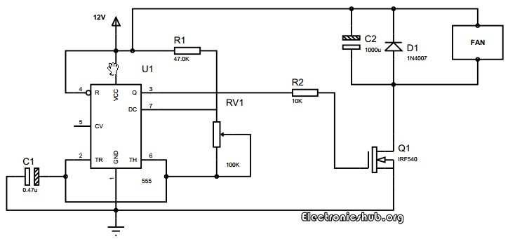
In this circuit, the DC motor is
operated by a 555 integrated circuit. The IC 555 in this circuit is
being operated in astable mode. In this mode, the circuit can be used as
a pulse width modulator with a few small adjustments to the circuit.
The frequency of operation of the circuit is provided by the passive
parameters of resistances and capacitances attached to it. The
resistance between pin-7 and pin-8, the resistance between pin-6 and
pin-7 and the capacitance between pin-2 and the ground govern the
frequency of operation and duty cycle of the ic 555 in astable mode. The
duty cycle is governed by the resistor which is in between pin-6 and
pin-7 of the IC 555 timer. So, by taking advantage of the circuits
working, we can change the 555 astable multivibrator into a pulse width
modulator by using a variable resistor instead of a constant resistor in
between pin-6 and pin-7.
Read the following Post also: Water Level Alarm Using 555 Timer
One of the best things about this
circuit is that we can make it work as an astable multivibrator with
little hardware and by little cost which can save both the cost involved
in making it as well as the space on the printed circuit board is
saved. if we want a sophisticated pulse width modulator which works more
accurately and which can have more adjusting capabilities, then it is
better to use a microcontroller based pulse width modulator than the one
which we are using now. However, the circuit or the application for
which we are using a pulse width modulator is not so sensitive and hence
does not demand so much of accuracy. In such a case, the circuit which
we are using with a bare IC 555 is better as it saves our monetary as
well as space resources in building the circuit.
The duty cycle of the circuit can be
changed by changing the resistance between pin-7 and pin-6. If we
increase the duty cycle, the speed of the motor increases and if we
decrease the duty cycle, the speed of the motor decreases.
Are you interested to do this project using microcontroller? Then go to the post – How PWM based DC Motor Speed Control Circuit Works using Microcontroller?
0 comments:
Post a Comment